A 3 8 cable clamp refers to the diameter capacity of the cable clamp, indicating that it can effectively secure cables or wires with a diameter of up to 3/8 of an inch.
Cable clamps are used to organize and secure cables or wires in various applications to prevent tangling, damage, or interference.
- Light-duty clip, not for use in heavy-duty applications
- Galvanized finish for corrosion protection
- Meets Federal Specification FF-C-450, Type 1, Class 2
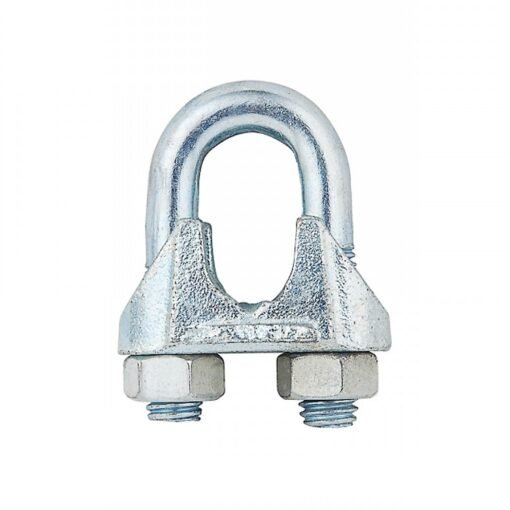
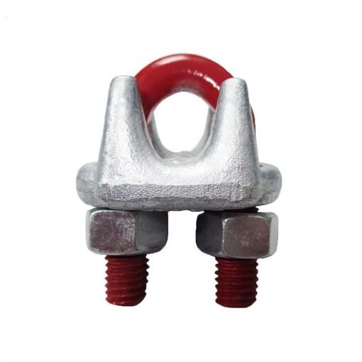
US Type Malleable cable clamp is produced according to Federal Specification FF-C-450 Type 1 Class 2. The clips can be zinc plated, hot-dip galvanized upon request. It’s also called wire rope clip, U Clip, U Clamp, U Bolt, which is used to form the wire rope loop or eye.
Key Features Of 3 8 Cable Clamp
1. Material: 3 8 cable clamp are typically made from malleable iron, which is a type of cast iron that has been heat-treated to increase its ductility and malleability. This material provides good strength and durability while maintaining some degree of flexibility.
2. U-Bolt Design: Like other wire rope clips, malleable wire rope clips have a U-bolt shape that allows the wire rope to pass through it.
3. Saddle Plate: The clips have a saddle plate that fits around the base of the U-bolt and sits on top of the wire rope.
4. Nuts: Two nuts are used to secure the U-bolt and saddle plate together, creating a tight grip on the wire rope.
The Installation
The installation of a 3 8 cable clamp follows a specific process to ensure proper performance and safety. Here are the general steps:
1. Positioning: Position the U-clamp around the wire rope where the loop or connection is desired.
2. Saddle Placement: Place the saddle plate on top of the wire rope, centered over the U-bolt.
3. Nuts Installation: Screw the two nuts onto the threaded ends of the U-bolt and tighten them alternately. Ensure they are tightened to the specified torque, following the manufacturer’s guidelines.
4. Check Tightness: After installation, check the tightness of the nuts regularly, especially during the initial period of use and periodically thereafter, to ensure they remain secure.
| SIZE MM | A MM | B MM | C MM | D IN | E MM | F MM | G MM | W/100PCS KGS |
| 1/8 | 11 | 14 | 14 | 1/4 | 10.8 | 22 | 20 | 1.54 |
| 3/16 | 14.5 | 15 | 16 | 1/4 | 13 | 26 | 24 | 2.5 |
| 1/4 | 17 | 18.5 | 20 | 5/16 | 15 | 32 | 31 | 5.3 |
| 5/16 | 18.3 | 20 | 22 | 5/16 | 16 | 35 | 34 | 5.9 |
| 3/8 | 22.5 | 22 | 27 | 3/8 | 22 | 40.5 | 41 | 11 |
| 7/16 | 24 | 23 | 30 | 3/8 | 22 | 43 | 42 | 11 |
| 1/2 | 27 | 26 | 35 | 7/16 | 23.3 | 49 | 53 | 18.5 |
| 9/16 | 30 | 26.5 | 40 | 1/2 | 27 | 52.5 | 54 | 25 |
| 5/8 | 33 | 28 | 40 | 1/2 | 28 | 57.5 | 59 | 28 |
| 3/4 | 34.5 | 32 | 42 | 9/16 | 34 | 61 | 68 | 35 |
| 7/8 | 41 | 37 | 46 | 5/8 | 38 | 71 | 78 | 53 |
| 1 | 45.5 | 42 | 55 | 5/8 | 43 | 77.5 | 87 | 66.6 |

Reviews
There are no reviews yet.